What Is an Inverter and How Does It Work? Inverter Basics
This article typically includes descriptions of inverters, their basic operation, and classification. You can learn about the inverter’s basics by reading the entire post.
What Is an Inverter?
A power inverter is a system that converts direct current (DC) to alternating current (AC). It is a converter.
You may be familiar with another type of converter called a rectifier, which converts alternating current to direct current. Most of our electronic equipment contains a rectifier.
In this case, the conversion cycle is reversed as opposed to what happens in the rectifier.
In general, an inverter is an electrical device that can convert a direct current (DC) to an alternating current (AC) at a given frequency and voltage.
Let’s take a look at how it works.
How Does an Inverter Work?
Before we get started, let’s take a look at the inverter’s main components. Then, it is easy to understand how an inverter works.
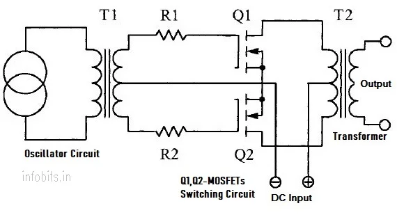
A power inverter system is made up of a direct current (DC) source, a rectifier, a pulse-generating circuit (Oscillator), a control circuit, a drive circuit, a switching circuit, and a step-up transformer.
Depending on the battery voltage, the charging transformer reduces the mains voltage from 230 to 12V/24V.
Transformerless inverters are now available on the market as a result of the introduction of new technology.
The DC source is typically rated at 12V or 24V.
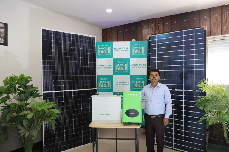
Other than the solar power systems where the DC source is the solar panel output, the inverter is frequently used as a stand-alone unit.
In an off-grid solar system, however, the DC source is either a battery or a solar panel.
Different stages are used to convert direct current (DC) to alternating current (AC).
First, an input DC voltage (from a battery, rectifier, or solar panel) is passed through a switching circuit that switches it at a specific frequency. The power transistor, or MOSFET, is a critical component of the switching circuit.
The oscillator’s circuit controls the switching frequency. The switching transistors’ variable output is fed to a step-up transformer with a primary voltage level equal to the DC voltage of the battery or rectifier. As previously stated, it is usually 12V or 24V.
The charging circuit, switching circuit, and inverter circuit are all part of the inverter main board. The inverter circuit is used here to perform the critical inverter function.
This transformer’s secondary voltage rating is typically 230 V or the country-specific voltage. The transformer used here is typically a push-pull primary centre-tapped one.
The centre point is common in this case, and DC is alternately switched to pass through each half of the windings.
When one transistor is turned on, and the other is turned off for a brief period, DC moves in only one direction.
The other transistor is then turned on while the first is turned off, causing the current to flow in the opposite direction.
Depending on the voltage ratio, the alternating component of the primary voltage induces an AC voltage on the secondary windings of the transformer. It is available in either 12V/230V or 24V/230V configurations. Here, 230V is the inverter output voltage.
The number of times the MOSFETs are turned on and off is determined by the frequency required for the AC output voltage.
In most countries, the standard alternating current voltage frequency is 50 or 60 Hertz. If we want a 50Hz power supply, we must turn each transistor on and off 50 times.
The power supplied by alternators or local power authorities has a pure sine waveform.
However, the standard output of a DC-to-AC converter is a square waveform. As a result, an additional circuit is used to improve the output waveform.
Inverter Types
Inverters are classified primarily based on many factors, including the waveform output, mode of operation, and whether or not they are connected to the electrical grid.
Inverter Types Based on the Output Waveform
Inverters are classified as Square Wave, Modified Square Wave, or Sine Wave, depending on the output waveform.
1. Square Wave Inverter
Square wave inverters are simpler and less expensive. However, its working efficiency is low, and the THD is greater than 45 per cent.
As a result, most appliances are damaged by the power supply’s square waveform. This type of inverter is rarely used.
2. Modified Square Wave Inverter
The modified square wave inverter is a better version of the square wave inverter.
The gross harmonic distortion is only about 24% in this case. Most electronic devices are not harmed by it.
A modified square wave inverter, on the other hand, can cause a buzz or distracting humming noise in some devices.
3. Pure Sine Wave Inverter
The accurate sine waveform has the highest quality, with less than 3% THD. Medical devices and laser printers require a pure sine wave power supply.
Pure sine wave power is provided by inverters used in on-grid or grid-tied applications.
However, a pure sine wave system is more expensive than a square or modified square wave system. The true sine waveform is now used in the majority of commercially available power inverters.
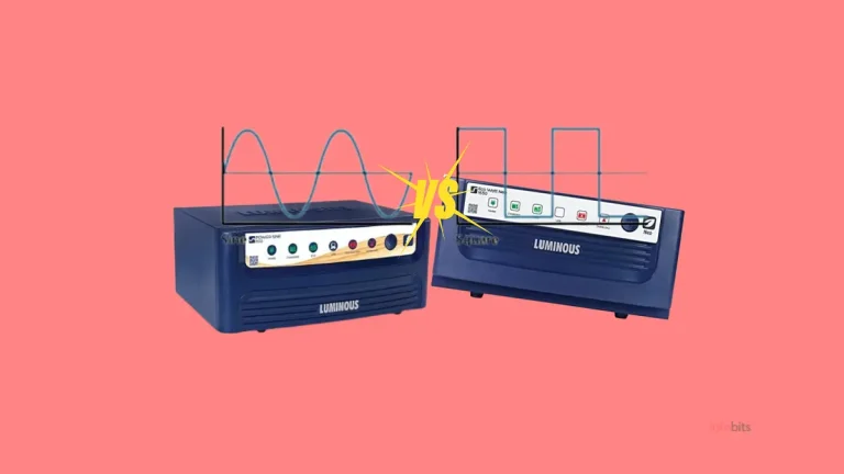
Related: Sine Wave Inverter vs Square Wave Inverter: Understanding the Differences
Inverter Types Are Based on the Mode of Operation
As previously stated, inverters are classified into three types based solely on their mode of operation: stand-alone inverters, solar inverters, and hybrid inverters.
Stand-Alone Inverters
This is the basic unit, as the name implies, and it operates in the common form.
When the main power supply fails, it provides backup power for your loads. This is made up of only the battery and the inverter.
When the main power supply is available, the battery is charged.
Solar Inverters
A solar inverter is merely a standard inverter, but its input DC source is a solar panel. Furthermore, there is no provision for a battery input connection.
Hybrid Inverters
It is a combination of standalone and solar inverter systems.
The DC input, in this case, comes from both the battery and the solar panels.
This hybrid system has the advantage of being able to be used with any independent DC source, such as a battery or a solar panel.
The other advantage of this type is that, in addition to being powered by the grid, the backup battery can also be charged by the solar panel.
In addition, when solar power is available, most of your appliances will run on it. This would result in lower monthly energy bills.
Inverter Types Based on the Power Grid Connection
Again, depending on whether or not the main grid is supplied, these inverters are classified as on-grid (tie grid) inverters or off-grid inverters.
On-Grid Inverter
The type of inverter that feeds into the main electrical distribution line is referred to as an on-grid or tie-grid inverter.
To put it another way, its output is linked to the main grid via a net metering system. Excess energy generated by your solar power system is fed back into the grid.
In an on-grid system, a pure solar inverter (without battery backup) is typically used.
During power outages, an interlock in the on-grid solar power system prevents the solar panel output from being provided.
The local electricity authority strictly controls and approves the installation of an on-grid power system.
Off-Grid Inverter
Off-grid inverters are those whose output is not connected to the power grid, making it a self-contained system.
The installation of an off-grid power system does not require prior approval from the local utility company. This system makes use of a hybrid inverter.
Read our in-depth article on the difference between on-grid and off-grid solar systems.
Related: How to Select the Right Inverter and Battery for Home in India?
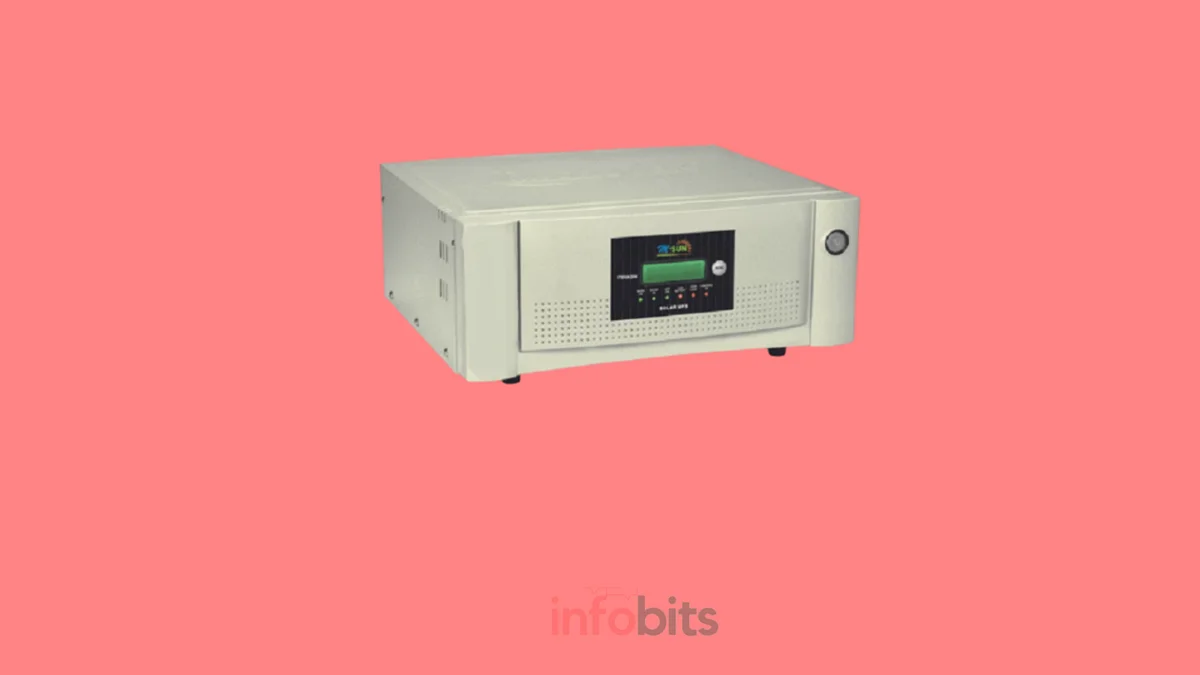
Use of an Inverter as a UPS
Inverters are frequently used in UPS mode to provide a continuous power supply, such as in computer systems.
However, they differ slightly in terms of internal design. When the mains power is available, the DC input source is from the rectified AC mains, and when the mains power fails, the DC input source is from the batteries.
As a result, there is no time lag when switching from the main power supply to the battery source and vice versa.
However, there is a time lag when the change is made in traditional systems that do not have a UPS mode. Because the battery is only connected to the switching circuit’s input when the main power fails.
Three-phase Inverter
A three-phase inverter, as the name implies, can provide three-phase (3ph) voltage and current.
A three-phase inverter converts direct current to three-phase alternating current. Its three arms are generally deflected at a 120° angle to produce a three-phase alternating current supply.
Three-phase inverters are connected across the same DC source, and their pole voltages are equivalent to those of a one-phase half-bridge inverter.
Related: Is It Worth Buying a Three-Phase Inverter?
Applications of Inverters
These are used in a wide range of applications, including tiny car adapters for the office, household applications, and large grid systems.
- These can function as stand-alone inverters.
- These are suitable for use in solar power systems.
- Inverters can function as Uninterruptible Power Supplies.
- An inverter is the fundamental component of an SMPS ( Switched Mode Power Supply).
If you feel that this article about inverter basics is helpful, please share this information with your friends and family.
Sign up for our free newsletter to stay updated on the latest deals, offers, and ebooks.
Don’t forget to like and follow us on Facebook and Twitter for the most up-to-date information.
Subscribe to be the first to learn about new information